
How to Fix a Power Tool Trigger Switch: For Major Brands
This post contains affiliate links. As an Amazon Associate, we earn from qualifying purchases.
To fix a power tool trigger switch, you need a multimeter to confirm it’s dead, then follow the manufacturer’s specific reconnection method, push-in terminals on older Foredom switches require a 1.3mm pin for release, and for cut wires, the strands should be soldered to fuse them together, while Milwaukee’s 23-66-1231 kit mandates all soldered connections with no loose strands.
That specificity is the line between a repair that lasts and one that fails in two weeks. A generic “swap the wires” approach ignores the two main switch designs: spring-clamp terminals you push a pin into, and direct-solder tabs you heat and flow. Mix them up, and the connection either rattles loose under vibration or overheats and cooks the switch. Knowing how to fix a power tool trigger switch correctly depends on identifying which type you have.
What follows: the diagnostic step every forum post skips, the exact tool specs from factory bulletins, and the one polarity mistake that instantly destroys a new switch. You’ll walk away knowing whether your switch is salvageable and the exact method for how to fix a power tool trigger switch so it holds.
Key Takeaways
- Test with a multimeter first, a switch showing infinite resistance (OL) at rest and no change when pressed is dead; a reading under 1 ohm that changes indicates a different problem.
- Match the connection type to your tool, older Foredom switches use push-in, spring-clamp terminals requiring a 1.3mm pin for release, while Milwaukee’s modern kits demand all soldered connections.
- Draw a wiring diagram before disconnecting anything, the single most common point of failure is crossing wires on reassembly, which can overheat and destroy a battery or motor in seconds.
- Brand service bulletins override general advice. Milwaukee’s 23-66-1231 kit ships with known missing wires and unsoldered LEDs; you must follow their 2009 wiring instruction to correct it.
- Polarity matters on DC tools, incorrectly crossing the long and short motor leads on a Milwaukee 0822-24 model will damage and destroy the new switch immediately.
Before You Start: Tools and Safety
This isn’t electronics hobby work. You’re dealing with high-current DC circuits that can overheat a lithium battery pack to thermal runaway if shorted. The first step is always to remove the battery or unplug the tool. Verify it’s dead with a trigger pull, no sound, no movement.
You need a few specific tools beyond a screwdriver set. A multimeter is non-negotiable for diagnosis. A soldering iron with a fine tip and appropriate solder is required for any repair involving Milwaukee’s service kits or preparing cut wires for Foredom push-in terminals. For the Foredom terminals, you also need a 1.3mm (.05in) pin or jeweler’s screwdriver blade, a paperclip is too soft and will bend.
Before you start: A crossed wire on a DC cordless tool powers the circuit backwards. The battery overheats quickly upon trigger pull, and the tool’s MOSFETs can fry. Draw a diagram.
Keep a small tray for screws and take phone photos after each disassembly layer. Plastic clips inside tool housings are brittle when cold; let the tool sit at room temperature before prying.
Testing the Switch with a Multimeter
Ever wondered why your drill just stopped, but the battery charges fine? The trigger switch is the first suspect. A multimeter tells you for sure.
Set the meter to the resistance (ohms, Ω) setting. Identify the two main terminals on the switch, these are the ones that complete the circuit to the motor. Place a probe on each. A healthy, unpressed switch should show infinite resistance (often displayed as “OL” for open loop). Now, press and hold the trigger fully. The reading should drop to a very low resistance. That indicates the internal contacts are closing cleanly.
If you get infinite resistance even with the trigger pressed, the switch is dead, internal contacts are burnt or broken. If you get a significant resistance reading at rest, you may have carbon tracking or dust buildup inside creating a partial short. This can cause the tool to run intermittently or only at full speed.
| Multimeter Reading | Switch Condition | What It Means |
|---|---|---|
| OL at rest, <1Ω when pressed | Healthy | Internal contacts are clean and operating correctly. |
| OL at rest, OL when pressed | Dead / Open Circuit | Contacts are burnt, broken, or not making contact. Replace switch. |
| 1-10Ω at rest, <1Ω when pressed | Contaminated / Partially Shorted | Dust or carbon debris is bridging contacts. May be cleanable. |
| Any reading at rest (e.g., 50Ω) | Failing | Significant internal corrosion or wear. Replacement recommended. |
This test isolates the switch from battery or motor problems. If the switch checks out, your issue lies elsewhere, a topic our guide on common causes of sparking covers in detail.
The Two Main Trigger Switch Designs
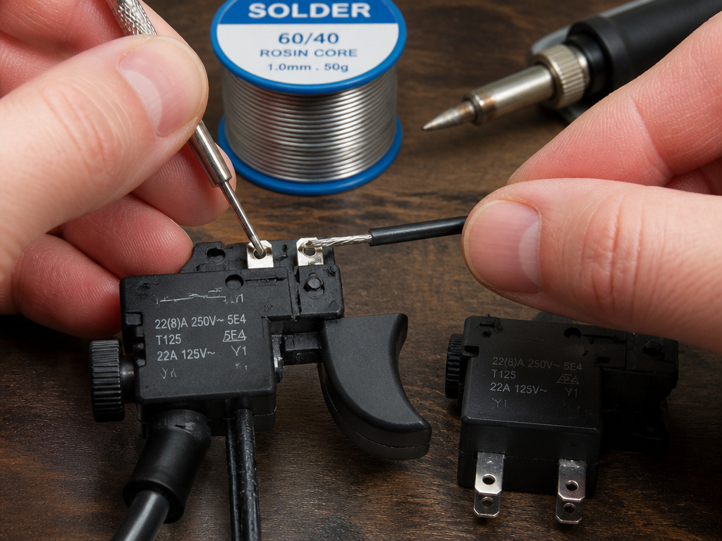
Power tool switches boil down to two connection methods. Using the wrong one guarantees a comeback.
Spring-Clamp (Push-In) Terminals are common on older professional tools, like Foredom flex-shaft controls. The wire inserts into a hole where a spring metal clip grips it. Foredom’s instructions are precise: to remove wires, insert a 1.3mm (.05in) pin or jeweler’s screwdriver blade all the way into the terminal socket to release the clamp. Pull the tool and wire out together. If the wire is cut, you must strip it back exactly 8.25 mm (5/16 in), then apply solder to the stripped ends to fuse the strands together before pushing it back in. This keeps individual strands from folding over and losing grip.
Direct-Solder Tabs are the standard for most modern cordless tools, like Milwaukee’s service kits. Here, wires are soldered directly to metal tabs on the switch. The factory specs are unforgiving. For the Milwaukee 23-66-1231 Switch Service Kit, the bulletin states: “All connections to be soldered. No loose wire strands, solder beads, or solder bridges are permissible.” The required strip length is exact: wires #8 (Black) and #9 (Red) get stripped both ends to .20”.
Where this goes sideways: Assuming all switches are the same. Soldering a wire meant for a push-in terminal makes it too thick to seat, and the connection overheats. Not soldering strands for a push-in terminal lets them spread, and the connection fails from vibration.
The repair process for how to fix a power tool trigger switch forks here. Your first job after diagnosis is to identify which system you’re working on.
Step-by-Step Repair and Replacement
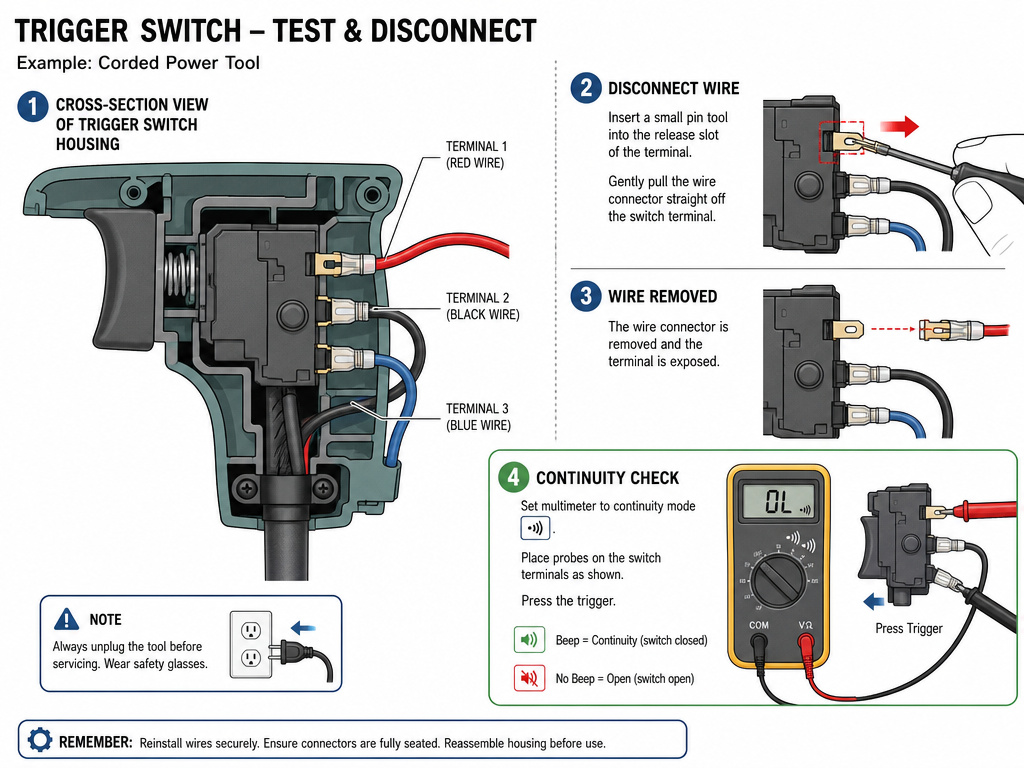
Once you know the switch is bad and you have the correct replacement, the physical work follows a clear sequence.
Step 1: Access the Switch
Remove the housing screws. Most tools split into two halves. Note any screws under labels or rubber grips. Inside, you may find a forward/reverse lever or lock button that must be removed before the switch slides out. Keep these small parts in your tray.
Step 2: Document and Disconnect
This is the most critical point. Draw a diagram. Label each wire color and its terminal position. Take a clear photo. For push-in terminals (Foredom), use your 1.3mm pin to release each wire. For soldered tabs, use a soldering iron and desoldering braid or a pump to cleanly remove each wire. Do not force or cut wires unless absolutely necessary, cutting creates more work later.
Step 3: Install the New Switch
Place the new switch in the mounting bracket. Reconnect the wires one at a time, following your diagram.
- For push-in terminals (Foredom): For cut wires, Foredom advises soldering the strands together before pushing the wire all the way in until no bare wire is exposed. Tighten any screw terminals (on newer Foredom switches, Terminal 1 has a screw). Then, pull on each wire to confirm it’s secure.
- For solder tabs (Milwaukee): Strip to the exact length specified. Apply heat to the tab, then flow solder onto the joint, not the iron tip. For the Milwaukee 0822-24 model, solder should be applied to a maximum of .23. Use a 3/4″ piece of black heat shrink tubing over the joint if specified.
Step 4: Reassemble and Test
Before closing the housing, do a continuity test with your multimeter again to ensure no shorts. Reinstall any levers or buttons. Snap the housing halves together and secure screws. Insert a battery or plug in the tool. Test the trigger at low speed in a safe direction.
A repair often reveals other wear. If the tool runs but sounds gritty, the next wear item is usually the carbon brushes. Replacing them proactively can prevent motor damage.
Brand-Specific Quirks and Common Failures
General advice fails on the specifics. Here’s what the factory bulletins say you’ll actually encounter.
Foredom Electric Company outlines the generational difference. On older switches, all terminals are push-in, spring clamp type. On newer switches, Terminal 1 has a screw for fastening the wire lead; the rest remain push-in. This mix means you need two tools on the bench.
Milwaukee Tool has documented edge cases. Their October 2009 bulletin for the 23-66-1231 kit states that “in a few instances” the kit shipped minus the 14 gauge red & black switch wire and LED wires may not be soldered to the terminal box.” You must use their wiring instruction to add and solder them. For their 0822-24 model, polarity is critical: the switch is destroyed if wired incorrectly. The long lead goes to the upper motor terminal and the short lead to the lower motor terminal, and the leads must be crossed in the terminal block as illustrated.
DeWALT, as noted by eReplacementParts, uses Variable Speed Range (VSR) switches in models like the dw987. These switches are often compatible across several DeWalt cordless tools, but the wires use a clamping system. The warning is universal: crossing wires on a DC tool causes immediate overheating.
| Brand & Model | Switch Type | Critical Specification | Known Issue / Quirk |
|---|---|---|---|
| Foredom (Older) | Push-In Spring Clamp | Remove wires with 1.3mm pin. | All terminals are push-in. |
| Foredom (Newer) | Mixed (Screw + Push-In) | Terminal 1 has a screw. | One screw terminal, rest push-in. |
| Milwaukee 23-66-1231 | Soldered Tabs | All connections soldered, strip to .20”. | Kits sometimes missing wires/unsoldered LEDs. |
| Milwaukee 0822-24 | Soldered Tabs | Polarity-sensitive; leads must be crossed. | Incorrect wiring destroys switch instantly. |
| DeWALT dw987 | VSR with Clamps | Compatible with other DeWalt tools. | Crossed wires overheat battery. |
These aren’t suggestions. They are the steps that, if skipped, turn a simple swap into a parts-order backlog.
Soldering and Connection Best Practices
If your repair involves solder, technique is everything. A cold joint fails under vibration; a blob creates a short.
Use a temperature-controlled iron set to an appropriate temperature for the solder being used. Tin the tip with a tiny amount of fresh solder. Hold the iron to the switch tab and wire together for 2–3 seconds, then feed the 60/40 rosin-core solder into the joint, not onto the iron. The solder should flow smoothly and coat both parts, forming a concave fillet. Remove the solder, then the iron. Let it cool without moving.
For the Milwaukee 0822-24, where solder is specified at .23 MAX, this means a thin, consistent layer, not a dome. After soldering, inspect for bridges to adjacent terminals and any loose strands poking out. Conformal coating or heat shrink tubing is your friend. Milwaukee explicitly permits “heat shrink permissible on all soldered connections.”
I learned the hard way that skipping the post-solder inspection is a guarantee. A single stray strand bridging two terminals on a drill trigger hid until the first time the trigger was pulled at full speed. The pop and wisp of smoke took out the new switch and the control board. Now I inspect with a bright light and a magnifier every time.
Good soldering is a skill that translates to many repairs, like fixing a damaged power cord. The principles of a clean strip, proper heat, and solid mechanical support are identical.
Diagnosing Other Common Trigger Problems
Sometimes the switch tests fine. Here’s what else to check.
Battery/Charger Issues: Use your multimeter to check battery voltage under load (with the trigger pulled). A significant drop indicates a weak cell pack, not a switch problem.
Carbon Brush Failure: Worn brushes can cause intermittent operation or sparking inside the motor, mimicking a bad switch. Inspect them, our guide on symptoms of worn carbon brushes lists the specific signs.
Internal Dust Contamination: Fine dust can get inside a sealed switch, acting as an insulator. Spraying electronic contact cleaner (like CRC) into the switch mechanism while working the trigger can sometimes clean it. This is a temporary fix for a sealed unit; eventual replacement is likely.
Mechanical Bind: As seen in the YouTube transcript, a bent trigger lock or debris can physically block the trigger. This requires disassembly, cleaning, and gentle bending of plastic components back into alignment.
The process is diagnostic before it’s reparative. Isolate the component.
Should I Repair or Replace My Power Tool?
Before ordering parts, check if they’re even available. For some older tools, manufacturers discontinue specific switch assemblies, replacing them with newer service kits that integrate components like the PC board. The cost of a full switch and handle kit can be a significant fraction of a new tool’s price. Consider the tool’s overall value and your ability to perform the repair. If the repair requires soldering and you lack the tools or confidence, or if the replacement part cost approaches half the price of a comparable new tool, replacement often becomes the more practical choice. Always factor in the risk of incorrect installation, which can instantly destroy the new switch.
Frequently Asked Questions
What is a trigger switch for a drill?
It’s a variable-speed electronic switch, usually a Variable Speed Range (VSR) switch in modern drills. It regulates power from the battery to the motor based on how far you pull the trigger, and it often houses the forward/reverse selector.
Why is my drill chuck not rotating?
This is rarely the switch. First, check if the forward/reverse selector is stuck in the middle “lock” position. If it’s not that, the issue is likely a mechanical failure in the gearbox, clutch, or chuck assembly itself, not the electrical trigger.
What should you do if a power tool is not working correctly?
Always start with the simplest, safest checks: ensure the battery is charged and making good contact, or the cord is plugged in. Then, perform the multimeter test on the trigger switch as described. Systematic diagnosis prevents unnecessary repairs.
How does a drill switch work?
Inside the switch, pulling the trigger moves a contact plate across a resistive element (like a strip of carbon). This gradually lowers the electrical resistance, allowing more current to flow to the motor, which speeds up. At full trigger pull, the resistance is near zero, delivering full power.
The Bottom Line
Fix the switch by the book in your hand, not the one in your head. The Foredom .05in pin and the Milwaukee .20” strip length aren’t recommendations, they are the measured tolerances that keep a connection live through months of vibration and amperage spikes.
If you walk away with one action, let it be this: draw the diagram before you touch a wire. That five-minute sketch is the difference between a Saturday morning success and an afternoon spent guessing which red wire goes where while your new switch cooks itself.
The other truth is that a trigger switch failure is often a symptom, not the disease. A switch that died from a direct overload is one thing. One that failed from conductive dust ingress or a worn motor drawing surge current is a sign to check the brush symptoms next. Fix the root cause, or you’ll be back here sooner than you think.
