
How to Tram a Milling Machine: Step-by-Step DTI Process
This post contains affiliate links. As an Amazon Associate, we earn from qualifying purchases.
To tram a milling machine, you use a dial test indicator (DTI) mounted in the spindle to measure deviation from perpendicular across the table, then adjust the head’s tilt and nod until the readings match within your machine’s tolerance, often .001″ or less over a 4–6 inch sweep.
That .001″ number isn’t arbitrary. It’s the threshold where a misaligned spindle starts writing its signature on your work, a faint but measurable step between passes, a surface that looks textured even with a fresh end mill. A key part of setup is knowing how to tram a milling machine. Get it right, and the machine becomes predictable. Get it wrong, and you’re chasing ghosts in your setup.
What follows is the full breakdown: the tools you actually need, the step-by-step sweep-and-adjust routine that works on a Bridgeport or a benchtop mill, the specific torque values and tolerances that matter, and the machine-specific quirks that explain why your first attempt might not hold.
Key Takeaways
- Tram with a dial test indicator (DTI) with sufficient reach; a cheap holder or a wobbly mount will lie to you.
- For most manual mills, sources like Workforce LibreTexts advise adjustment if readings differ by more than .001″, while for precision work or Tormach mills, the target tightens to less than .0005″ over a 6-inch circle.
- Adjust by half the measured error because the head pivots between your indicator points; cranking the full difference overshoots every time.
- Re-tighten head bolts to the specified torque (often 50 ft./lbs.) and re-check, final tightening can shift your perfect tram by a few tenths.
- On a mill/drill, expect alignment to drift after moving the table; a 0.0005″ tram can degrade to 0.003″ with normal use, which is often still usable.
What Tramming Is (And Why You Can’t Skip It)
Tramming is aligning the rotational axis of your spindle to be dead perpendicular to the plane of your machine table. Think of it as squaring up the foundation before you build the house. If the spindle leans, even slightly, the cutter follows that lean. The result isn’t just a cosmetic flaw; it’s a fundamental geometric error that compounds.
A head out of tram doesn’t cut a flat pocket. It cuts a shallow wedge. The difference might be only half a thousandth across a four-inch part, but that’s enough to make a press-fit impossible and a sealing surface leak.
You’ll hear the term “nod” for front-to-back tilt and “tilt” for side-to-side lean. The goal is to zero both. The frequency? Check it at the start of any new project, after a crash, or if you share the machine. Some machinists do a quick verify every morning. It takes five minutes with practice and saves hours of rework.
The Tramming Toolbox: DTI, Square, or Specialty Tool?
You have three main paths, each with a different balance of cost, speed, and certainty.
| Tool | Best For | Speed | Key Limitation |
|---|---|---|---|
| Dial Test Indicator (DTI) | Most users, highest accuracy | Slow (5-10 min) | Requires interpretation, sensitive to setup |
| Spindle Square (e.g., Pro Tram) | Repeat checks, beginners | Fast (<2 min) | Cost, requires calibration check each use |
| Machinist/Cylinder Square | Rough check, quick verify | Very fast (30 sec) | Low accuracy, confirms major error only |
The dial test indicator is the default. You’ll need a DTI with sufficient resolution, a solid mounting arm that gives you adequate reach from the spindle center, and a clean, flat section of table, not a fixture plate or vise bed. The DTI method teaches you what the machine is doing and is central to learning how to tram a milling machine; it’s the skill builder.
A spindle square like the Edge Technology Products Pro Tram is a dedicated tool that fits in the collet. It has two opposite indicators. You lower it, watch both dials, and adjust the head until they match. It’s foolproof for getting the head square, but the manual notes you must check its calibration every time you seat it in the collet to account for seating inconsistency. It’s fast, but it doesn’t teach you the underlying process of how to tram a milling machine.
The machinist square or cylinder square is a quick visual check. Hold it against the spindle and look for light gaps. It’s only good for spotting a head that’s wildly out, more than a few thousandths. For the precision this work demands, it’s a preliminary step, not the final verdict.
The Step-by-Step DTI Tramming Process
Here’ s the full sequence, from a dirty table to a signed-off tram. The goal is a repeatable ritual, not a frantic adjustment.
1. Prepare the Machine.
Clean the table thoroughly. Remove any vise, fixture plate, or swarf. This step is essential. The Tormach knowledge base states you must read the indicator off the machine table only, not a fixture plate. Any intermediate surface adds its own error. Ensure the machine is reasonably level; a severely twisted base makes tramming a moving target.
2. Mount and Zero the Indicator.
Secure your DTI in a holder and mount it in the spindle. The needle should be parallel to the direction of travel. Pick a spot near the edge of your clean table area. Gently raise the table until the indicator contacts and the needle moves. Sources disagree on preload: the Open Oregon Pressbooks guide says raise until the indicator reads between 0.005″ to 0.010″, while the Pro Tram manual says depress both indicators by about 0.050″. The key is consistency, use enough preload so the needle stays on scale during the full sweep, but not so much that you risk bending the stylus. Rotate the dial face to zero the needle at this first point.
3. Sweep and Record.
Slowly rotate the spindle by hand 180 degrees to the opposite side of your sweep circle. Note the reading. A positive number means the table is higher at that spot relative to your zero; a negative (needle moves opposite direction) means it’s lower. Now repeat for the front-to-back (nod) axis. You now have four numbers: front, back, left, right.
4. Interpret and Adjust.
This is where most guides stop, but it’s where your brain has to engage. The rule from the Workforce LibreTexts guide is clear: adjust by half the amount the head is out of tram. If your left read 0 and your right read +.002″, the head is leaning to the left. To correct it, you need to move the right side of the head down by .001″. Why half? The pivot point is between your two measurement points. Moving one side affects both readings.
For tilt (side-to-side), loosen the four bolts on the face of the mill head. Use the adjustment screws to nudge the head. For nod (front-to-back), loosen the three or six bolts on the side of the head at the ram. Make your half-correction, snug the bolts lightly, and re-sweep to check.
5. Final Tighten and Verify.
Once you’re within tolerance, it’s time for final torque. The Workforce LibreTexts guide specifies tightening the tilt fasteners to 50 ft./lbs. and the nod fasteners to 50 ft./lbs. The Open Oregon Pressbooks guide advises a different approach: tighten the four front bolts to just beyond hand-tight (about ¼ turn past). This is a key disagreement.
After tightening, sweep all four points again. It’s common for the final cinch to pull the tram out by a few tenths. If it’s still within tolerance, you’re done.
Common mistake: Cranking the adjustment the full amount shown on the dial. That overshoots because you’re pivoting around a point between the indicators. Dial in half, check, and iterate.
Tolerance Targets: When is “Good” Actually Good?

Here’s where the sources don’t agree, and your machine type decides which rule to follow.
| Source / Machine Type | Tolerance Trigger | Target |
|---|---|---|
| Workforce LibreTexts (General Manual Mill) | Difference > .001″ | Readings equal at all four points |
| Open Oregon Pressbooks (Educational) | N/A | All measurements within 0.002″ |
| Tormach Knowledge Base (Precision CNC) | N/A | < .0005″ movement in a 6″ circle |
For a standard manual mill used for general fabrication, the .001″ rule is practical and achievable. If your sweep shows a .0008″ variation, you’re fine. Chasing tenths beyond that on a machine with worn ways is an exercise in frustration.
For a Tormach PCNC 1100 or other precision benchtop CNC, the factory expects better. Their .0005″ over 6 inches target is for spindle tram, which assumes a very rigid, well-leveled machine. It’s a good goal, but recognize the equipment difference.
The Open Oregon 0.002″ tolerance is a common educational shop standard, forgiving enough for students to achieve, tight enough to teach the principle.
Your project decides the final call. Milling a flat plate for a welding fixture? .001″ is plenty. Surfacing a mold core for injection molding? Get as close to that .0005″ as your machine can reliably hold.
Machine-Specific Quirks: Bridgeport vs. Mill/Drill
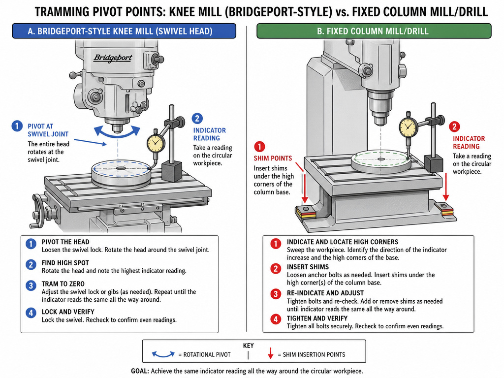
Not all mills adjust the same way, and the standard DTI method assumes a certain machine architecture.
On a knee mill with a swiveling ram head, the adjustment is direct. You loosen bolts and turn screws that pivot the head on its mounts. The DTI readings correlate directly to the needed adjustment. It’s a linear, predictable system.
On a mill/drill, the head is fixed to a column. Tramming requires shimming between the column and the base. Rick Sparber documented a key point: there is no direct correlation between DTI readings and shim thickness. The geometry is less direct. Also, the alignment may not be stable. In his Tramming a Mill/Drill guide, Sparber achieved a near-perfect 0.0005″ error, but after moving the table and head, it degraded to 0.003″. That shift is the reality of a less rigid structure. The standard fix is to loosen the column bolts and add shims at the high corners, but expect to iterate.
Where this goes sideways: Assuming a perfect tram on a mill/drill will stay perfect. The structure flexes. A 0.003″ error after movement is common and often still workable for non-precision tasks. Know your machine’s limits.
Troubleshooting Poor Tram Results
You followed the steps, but the needle dances wildly or you can’t get the numbers to settle. Before you blame the indicator, check these culprits.
Spindle Runout: Is your DTI holder running true? Chuck a test bar and sweep it with another indicator. If the spindle itself has significant TIR (Total Indicator Runout), you’re measuring that wobble plus the tram error. You need to either compensate for runout in your readings or address the runout first (bad collet, dirty taper).
Loose Gibs or Worn Ways: A milling head that rocks on worn ways will never tram consistently. Lock the knee and saddle. If you can feel play, tramming is the least of your problems. Tighten the gibs to manufacturer spec as a first step.
DTI Holder Rigidity: A long, thin extension arm will deflect under its own weight, giving false readings. Use the shortest, stoutest holder that gives you the required reach. A magnetic base on the spindle housing is often stiffer than a collet-held setup.
Dirty or Damaged Pivot Points: On a Bridgeport, the mating surfaces between the head and ram must be clean and burr-free. A fleck of swarf or a ding can cant the head unpredictably. Clean with a solvent and a Scotch-Brite pad, and inspect for damage.
If you’ve checked all this and the tram still won’t hold, you might be at the mechanical limit of the machine. This is when knowing the difference between a mill/drill and a true milling machine matters. The former has inherent flexibility; the latter, when in good repair, should hold a tram reliably.
Frequently Asked Questions
What is tramming a milling machine?
Tramming is the process of adjusting the milling machine head so that the spindle is perfectly perpendicular to the table surface in both the left-right (tilt) and front-back (nod) directions. It ensures that cutting tools travel straight up and down, producing flat, square work.
How often should I tram my mill?
Tram at the start of any new, precise project, after a crash or heavy impact, and if you share the machine with others. Many machinists do a quick check daily. For light, repetitive work on a stable machine, a monthly check might suffice.
Can I tram a mill without a dial indicator?
For a rough check, yes, you can use a machinist square held against the spindle. For any precision work, no. The visual square method can only detect large errors (>.005″ or more). Accurate tramming requires the quantitative measurement of a dial test indicator or spindle square.
Why did my tram change after I tightened the bolts?
Final tightening applies stress that can slightly distort the head or its mounting. This is why the final verification sweep is a mandatory step. Some procedures, like the Open Oregon Pressbooks method, use lighter tightening (hand-tight plus a quarter turn) specifically to minimize this shift.
Is a spindle square better than a DTI for tramming?
Spindle square is faster and simpler, making it excellent for frequent checks. However, a DTI is more versatile, teaches you the fundamentals, and can diagnose other issues (like table flatness). For learning and deep setup, the DTI is the better tool. For production speed, the square wins.
The Bottom Line
Tramming isn’t a one-time setup. It’s a core maintenance skill, as fundamental as sharpening a chisel or tuning a tablesaw. The .001″ rule for manual mills is your guiding threshold, but let the job dictate the final tenths. Less precise work can live with a looser tolerance; a Tormach milling an aluminum fixture needs that .0005″ target.
The single most useful habit you can build is the post-adjustment verification. Tighten to spec, sweep the indicator one last time, and record the numbers in a machine log. That record tells you more about your mill’s stability than any spec sheet.
If your first attempts are frustrating, the numbers jump, the head seems to have a mind of its own, check the holder rigidity and spindle runout first. Those two issues mask more tram problems than any adjustment error. Once you see a consistent, repeatable sweep, the adjustments become predictable. And a predictable machine is a tool you can trust.
