
How to Size a Regenerative Blower: The 4-Step Method
This post contains affiliate links. As an Amazon Associate, we earn from qualifying purchases.
Sizing a regenerative blower means matching two numbers: the required airflow (in CFM or SCFM) and the system’s back pressure (in inches of water column, or H2O). You find these by defining your application’s flow demand, calculating or measuring the total resistance in your piping, then plotting that operating point on a manufacturer’s performance curve to select a model that lands in its efficient, safe zone.
Now, the tricky part everyone glosses over. Those curves are drawn for specific, standard air conditions, 70°F and sea level for some brands, 59°F for others. Your shop floor in Phoenix in July is neither. A key step in how to size a regenerative blower is applying these environmental corrections. If you skip the correction, the blower you buy may be significantly undersized before it even spins up.
What follows: a four-step process, a real-world example with numbers, and the two environmental limits that will wreck a correctly-sized blower if you ignore them.
Key Takeaways
- Always match CFM and pressure using a manufacturer’s performance curve, never just horsepower or a “similar” model.
- For continuous low-flow operation, install a bypass line; running a Spencer Vortex blower below the solid curve line causes overheating.
- Correct for your actual inlet air temperature using the manufacturer’s standard (e.g., Spencer’s 70°F or Republic’s 59°F); the difference between these standards changes air density enough to shift your operating point.
- Mounting orientation matters: Spencer’s VB055, VB075, and VB110 models are horizontal-only unless the factory approves a vertical setup.
- The axial clearance between impeller and housing is critical; one study finds a typical range of 0.1 to 0.9 mm across literature, while research for hydrogen blowers recommends 0.2-0.5 mm for a higher pressure coefficient.
The 4 Steps to Size Any Regenerative Blower
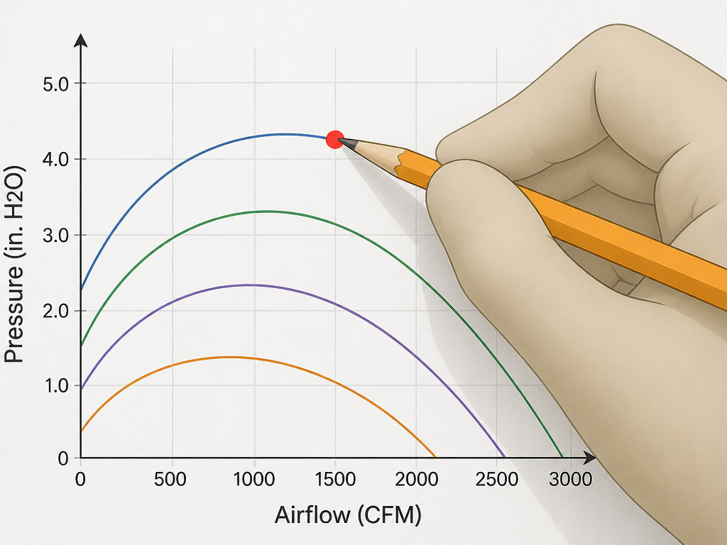
Forget the “pick a bigger one” advice. A regenerative blower isn’t a centrifugal fan; it has a narrow sweet spot. Miss it by a few inches of water column, and you get either not enough suction or a motor that cooks itself. The process is methodical, not magical.
Step 1: Define Your Required Airflow (CFM/SCFM).
What are you moving, and how much of it? For a vacuum pickup system, you might need 50 CFM to lift parts. For a pond aeration system, you calculate based on water volume and desired oxygen transfer. Write down the number. This is your target flow. The Spencer Turbine Company defines SCFM (Standard Cubic Feet per Minute) at industry standard conditions of 70°F, sea level, and 36% relative humidity. If your supplier uses that standard, stick with it. Republic Manufacturing bases its curves on 59°F air. That 11-degree gap isn’t trivial, it changes air density.
Step 2: Determine Your System’s Total Back Pressure (inches H2O).
This is where guesses go wrong. Back pressure is the sum of every restriction: pipe length, elbow friction, filter resistance, the water depth your bubbles must push through in a pond, even the heater element in a drying line. If you’re designing a new system, you calculate it. For an existing setup, the best method is to temporarily install a pressure gauge at the blower’s outlet (for pressure) or inlet (for vacuum) and measure it under load.
Common mistake: Estimating back pressure as “just a few inches.” A single tight-radius 90-degree elbow can add 2-3 inches H2O of resistance. For a system with low total pressure requirements, such an addition can represent a significant error.
Step 3: Plot Your Point on a Performance Curve.
Get the curve for the blower series you’re considering, like the Republic HRC line or Spencer Vortex VB series. The vertical axis is pressure (or vacuum), the horizontal axis is airflow. Find your required pressure on the Y-axis, move right to your required flow on the X-axis. That intersection is your operating point.
The goal is to have your point land on or just to the right of the curve’s peak for that model. Landing far to the left means low flow and high risk of overheating. Landing below the curve means the blower can’t reach your needed pressure. If you’re between two curves, the conservative pick is the larger model.
Step 4: Apply Real-World Corrections.
Your plotted point is for “standard air.” Now adjust for reality, which is a core part of how to size a regenerative blower. Is your inlet air hotter than 70°F? Hotter air is less dense, so the blower moves less mass. You need a larger model. Are you at 5,000 feet altitude? Thin air again reduces mass flow. Most manufacturers provide correction factors. If they don’t, consult the manufacturer for appropriate correction factors.
A Real-World Sizing Walkthrough
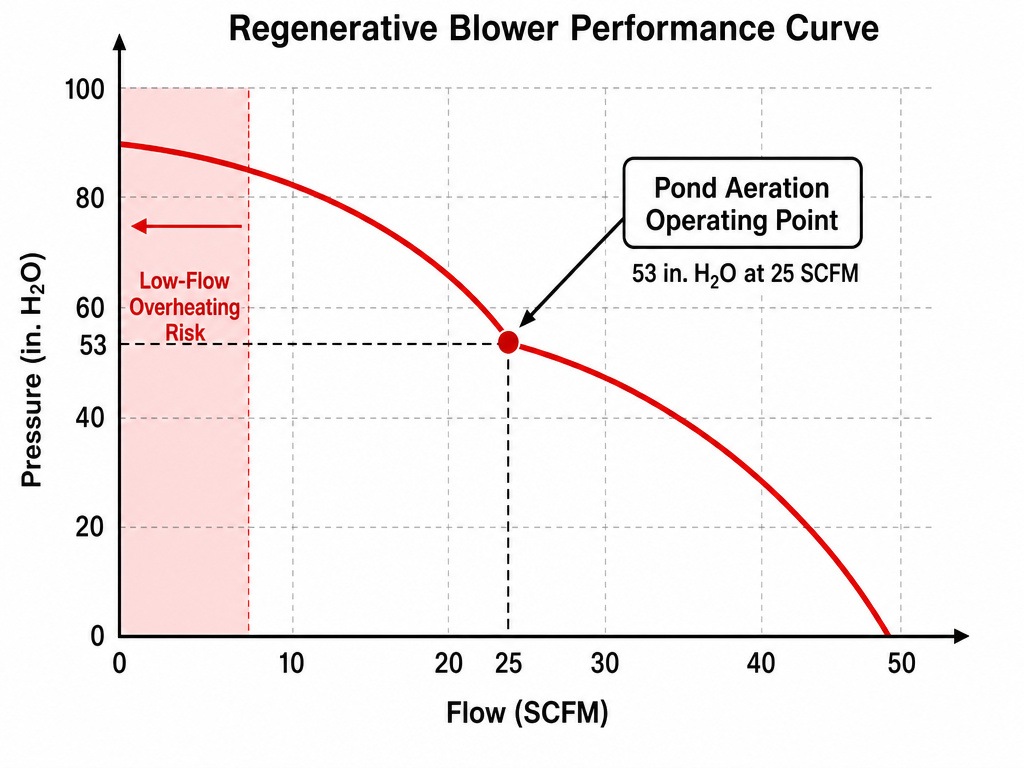
Imagine you need to aerate a 10,000-gallon pond. The goal is to keep dissolved oxygen above 6 mg/L, which calls for a certain amount of air per gallon per hour. After the math, you determine you need 25 SCFM at a pressure sufficient to push bubbles down to a diffuser sitting 4 feet deep.
Water depth is your primary back pressure. One foot of water creates a specific pressure resistance; you must calculate the static pressure based on the water depth and the appropriate conversion factor. For a 4-foot diffuser submersion, that’s 4 x 12 = 48 inches H2O of static pressure. Add another 5 inches H2O for pipe friction and diffuser resistance. Your total required pressure is 53 inches H2O at 25 SCFM.
You pull up the performance curve for a Republic HRC750 (60 Hz model), a key document in the how to size a regenerative blower process. Its curve shows it can deliver 365 CFM at its rated pressure of 64 inches H2O, but the flow at a lower pressure like 53 inches H2O would be higher; you must consult the actual performance curve to find the exact value. Your operating point (53″ H2O, 25 CFM) is far to the left of its curve. This blower is massive overkill for flow, but more critically, running at such a low flow relative to its capacity puts it in the danger zone for overheating, especially if it’s a Spencer Vortex model without a bypass.
The better match is a smaller model, like a Spencer Vortex VB055. You would need to check its performance curve to find the flow delivered at 53 inches H2O. That’s close to your 25 SCFM target with a small safety margin. This is a fit.
| Application | Required Flow (SCFM) | Required Pressure (in. H2O) | Candidate Blower | Verdict |
|---|---|---|---|---|
| Pond Aeration | 25 | 53 | Republic HRC750 | Overkill; risk of low-flow overheating |
| Pond Aeration | 25 | 53 | Spencer Vortex VB055 | Good match; point lands on curve |
| Vacuum Conveying | 45 | 85 | Republic HRC800 | Needs curve check; likely good fit |
| Paper Handling | 15 | 30 | Smaller VB series | Likely fit, but check low-flow limits |
Environmental Limits That Flip the Script
You can nail the CFM and pressure match and still burn out a blower in a month. The install location writes checks the motor’s insulation class can’t cash.
Ambient Temperature and Humidity
Spencer Vortex blowers are rated for an ambient temperature between -5°F and 104°F at installation, with relative humidity not exceeding 80%. Republic states its performance curves are valid for inlet and ambient temperatures up to 77°F. See the disagreement? If your machine room hits 95°F, the Republic blower’s output is no longer guaranteed. The Spencer unit might run, but its motor insulation. NEMA Class F, rated to 265°F winding temperature, is now working much harder. Explosion-proof models use NEMA Class B insulation, which has a lower temperature ceiling.
Where this goes sideways: Installing a blower next to an oven or furnace. The ambient heat soaks into the motor casing, the internal temperature soars past the insulation rating, and the windings degrade. The failure isn’t sudden; it’s a slow bake that shows up as a loss of power over six months.
Corrosive or Explosive Atmospheres
This isn’t scare talk. The Spencer manual states: “Do not install the blower in any area which may have an explosive atmosphere or which may contain flammable gases or liquids.” It also warns against areas subject to corrosive liquids. Why? The cast aluminum housing and steel fasteners can corrode. More critically, for explosion-proof motors, the buyer must “check federal, state, and local codes” to see if the motor is even approved for the environment. A standard TEFC (Totally Enclosed Fan Cooled) motor is not explosion-proof. Using one in a paint booth or near solvent vapors is asking for trouble.
Mounting Orientation and Storage
Here’s a specific rule most miss: for Spencer Vortex models VB055, VB075, and VB110, the factory recommends horizontal mounting only. Vertical mounting requires checking with them first. The internal bearing lubrication and shaft loading are designed for one plane. Force it vertical without approval, and you risk premature bearing wear and an out-of-warranty repair. If you need to store a blower for a long time, protect it from dampness and dirt. A rusty shaft or a gummed-up impeller from sitting in a damp corner is a totally preventable failure.
How to Read a Performance Curve (It’s Not Just a Line)
The curve is a map of the blower’s capabilities. Think of it as a topographical map showing safe and dangerous terrain.
The Solid Line vs. The Dotted Line
On a Spencer Vortex curve, the solid line represents the continuous duty operating range. The dotted line extends to lower flows and higher pressures. Here’s the critical warning from their manual: “Operating at flows less than indicated by the solid line on its performance curve will cause overheating.” If your application requires continuous operation in that dotted zone, like maintaining a constant low vacuum for holding, you must “provide a bypass in the piping” and operate “at a lower pressure than the maximum operating pressure.” The bypass bleeds off excess air, increasing the flow through the blower itself and keeping it cool.
The “Knee” of the Curve
This is the point of peak efficiency for that pressure range. To the right of the knee, flow increases but pressure drops rapidly. To the left, pressure rises but flow diminishes. Your ideal operating point is just to the right of the knee. This gives you a slight buffer for system variability without tiptoeing into the overheating zone on the left.
Accounting for Tolerances
Manufacturers build in wiggle room. Republic notes a +/-10% tolerance on its performance curves (based on 59°F air at 29.91 inch Hg). Motor tolerances are +/-10% for fixed voltage three-phase, +/-5% for voltage range motors, and +/-5% for single-phase machines. The frequency tolerance is +/-2% maximum. This means your perfectly plotted point has a built-in margin of error. Don’t size so tightly that a 10% underperformance breaks your system.
Single-Stage vs. Two-Stage: When to Move Up
A single-stage blower has one impeller and one regeneration loop. A two-stage blower, like many in the Republic HRC line, has two impellers in series, with the air passing from the first stage to the second. This allows for much higher pressures.
The Pressure Threshold
As a rule of thumb, if your required pressure exceeds 100 inches H2O, you’re likely in two-stage territory. Look at the Republic HRC800: it’s a two-stage unit delivering 120 inches H2O of vacuum. The HRC1000 hits 158 inches H2O. For high-pressure applications like certain pneumatic conveying or industrial vacuum systems, the choice between a single-stage vs two-stage blower is made for you by the pressure requirement.
The Heat Management Trade-Off
In a traditional two-stage design, the second stage (which handles the hotter, already-pressurized air) sits next to the drive-end bearing. This can cook the bearing grease. Some manufacturers may use designs intended to manage bearing temperatures; consult specific product information for details. When evaluating a blower, ask if it’s a traditional or swapped-stage regenerative blower design if you expect heavy use.
The Final Checklist Before You Buy
You’ve done the math, picked a model, and checked the curve. Stop. Run through this list. It catches the last 10% of failures.
- Low-Flow Plan: Will you ever run at less than 50% of the blower’s maximum flow? If yes, you need a bypass valve and piping. Period.
- Inlet Protection: For pressure applications, an inlet filter is cheap insurance. Spencer’s filters are rated at >99% efficiency for 10-micron particles. For vacuum applications, an inline filter or separator protects the blower. Their Vacuum Separator claims 98.9% efficiency at 2 microns.
- Electrical Headache: Verify your supply voltage (220-275V for many 60Hz models) and phase (single or three-phase). The +/-5% tolerance on single-phase means a low-voltage condition could stall the motor.
- Sound and Space: Blowers aren’t quiet. The HRC750 has specific operating characteristics; consult its specification sheet for sound level data. Do you have an enclosure or a remote location? Also, check the footprint. The HRC1000 is a substantial piece of kit.
- Warranty Clock: Spencer’s warranty is 18 months from shipment or 12 months from startup, whichever comes first. Don’t let a new blower sit in a crate for a year before installing it; you’re burning warranty time.
Impact of electrical power (50Hz vs 60Hz) on performance
Motor speed is directly tied to line frequency. A blower designed for 60Hz will run slower on a 50Hz supply, reducing its flow and pressure output. The performance curve shifts. You cannot simply use a 60Hz curve and assume it will work; you need the specific curve for your local power. Manufacturers design models for specific frequencies, and the motor’s tolerances are set accordingly. Republic Manufacturing notes a maximum frequency tolerance of +/-2% for its HRC Series. Operating outside this tolerance risks performance deviation and motor issues. Always verify the blower’s nameplate and performance data match your facility’s electrical service.
Heat generation and thermal management
Regenerative blowers generate significant heat, especially when misapplied. Operating at flows less than the minimum indicated by the solid line on the performance curve will cause overheating. For continuous low-volume operation on the dotted part of the curve, you must provide a bypass in the piping and run the blower at a pressure lower than its maximum. Ambient conditions matter; install the unit in an environment within its specified temperature range and ensure it has adequate ventilation. Never operate the blower without its motor cooling fan cover or impeller end cover, as these are critical for thermal management. Excessive moisture can also lead to electrical failure.
Frequently Asked Questions
How do I calculate the required CFM for my application?
You start with the application’s physics. For aeration, it’s based on water volume and oxygen demand. For vacuum conveying, it’s based on the material’s weight and conveying velocity. For a vacuum hold-down table, it’s based on the table area and required hold force. There’s no universal formula. Consult application guides from manufacturers or a specific guide for pond aeration to see the calculations in action.
What’s the difference between a regenerative blower and a centrifugal blower?
Centrifugal blower uses a single acceleration through an impeller to create pressure, excelling at high volumes and low pressures. A regenerative blower uses a multi-stage, regenerative acceleration in a side channel, achieving much higher pressures (often over 100 inches H2O) at moderate flows. They are not interchangeable. A full regenerative vs centrifugal comparison highlights the trade-offs.
How many CFM is a “good” blower?
There is no “good” CFM. A “good” blower is the one that matches your specific CFM and pressure requirements. A 400 CFM blower is useless if you only need 20 CFM, it will overheat. A 20 CFM blower is useless if you need 400 CFM, it won’t move enough air. Throw out the idea of a generic rating.
Can I use a regenerative blower as an air compressor?
Not really. While both move air, a regenerative blower produces lower pressures (typically under 4 PSI, or ~110 inches H2O) but at continuous, oil-free flow. An air compressor stores air at high pressure (90+ PSI) in a tank for intermittent, high-force use. They are built for different jobs.
How important is regular maintenance?
Critical for longevity. Simple blower maintenance like checking inlet filters, ensuring cooling airflow, and listening for unusual bearing noise can prevent catastrophic failure. These are workhorse machines, but they’re not fit-and-forget.
The Bottom Line
Sizing a regenerative blower is an exercise in matching hard numbers, not guessing. Get your required CFM and pressure as accurately as you can, measure the old system if it exists. Plot that point on the actual manufacturer’s curve. Then, and only then, apply the real-world knobs: correct for your hot inlet air, plan for low-flow scenarios with a bypass, and double-check the ambient limits printed in the manual.
If your pressure need creeps above 100 inches H2O, you’re now comparing single-stage vs two-stage designs. That’s a different ballgame with its own heat and efficiency trade-offs. But the core principle remains: the curve is the final judge. Let it tell you if you’ve got the right blower, because the sound of a wrongly sized motor straining is the sound of money and time burning.
