
How Does an Air Compressor Work: The Mechanics Explained
This post contains affiliate links. As an Amazon Associate, we earn from qualifying purchases.
An air compressor works by using a motor to drive a pump, which draws in atmospheric air and reduces its volume, thereby increasing its pressure. This compressed air is then stored in a tank or sent directly to a tool. The core principle is either positive displacement (trapping air and shrinking its space) or dynamic displacement (accelerating air to build pressure).
That definition covers the basics, but the real-world details—like why a 7 bar compressor squeezes air to one-eighth its original volume, or how much water condenses inside on a humid day—are what separate a functional tool from a misunderstood one. To understand this, it helps to ask: how does an air compressor work? The type of pump, the staging, and the supporting components all dictate what jobs a compressor can actually handle.
What follows is a breakdown of the mechanics, the major compressor types, and the critical numbers like CFM and duty cycle that determine whether a model will run your sander or just inflate tires, answering the core how does an air compressor work question. By the end, you’ll be able to read a spec sheet and know exactly what you’re getting.
Key Takeaways
- The only number that matters for tool compatibility is CFM at your required PSI; tank size just determines how long you can run before the motor kicks back on.
- Compressing air reduces its volume dramatically—at 7 bar(e) (about 100 psi), air is squeezed to one-eighth of its original size, which forces out massive amounts of water vapor.
- Positive displacement (piston, screw) is for high pressure; dynamic displacement (centrifugal) is for huge, continuous volume.
- You must drain the tank daily to prevent internal corrosion; in cold climates, this also stops freeze damage overnight.
- For a home shop, a smaller tank with a fast-recovery pump is almost always more useful than a giant, slow-filling tank.
The Core Mechanical Process: Intake, Compression, Storage
Forget the complicated diagrams for a second. Think of a bicycle pump. You pull the handle back (intake), push it forward while blocking the outlet (compression), and that pressurized air waits in the hose until you release it on the tire valve (storage and discharge). An industrial compressor just automates and scales this cycle.
The process is intake, compression, and storage. But the underlying physics are essential to explaining how an air compressor works. When you compress air, you pack the same number of gas molecules into a smaller space. This increases the pressure, but it also has two major side effects: the air gets hot, and it can’t hold as much water vapor.
According to Atlas Copco’s compressed air manual, a compressor working at 7 bar(e) gauge pressure compresses air to 1/8 of its original volume. This reduction also cuts the air’s ability to hold water vapor by the same factor, forcing liquid water to condense out inside your system.
That water is a big deal. The same manual notes a 100 kW compressor pulling in air at 20°C and 60% humidity will produce roughly 85 liters of water during an 8-hour shift.
Positive vs. Dynamic Displacement
These are the two fundamental families of air compression, and they solve different problems. You’ll choose your types of air compressors based on which method they use.
Positive Displacement is the most common, especially for workshops. It works by trapping a volume of air in a chamber and then mechanically reducing the size of that chamber. Piston compressors do this with a cylinder and piston; rotary screw compressors do it with two meshing screws. The pressure builds because the air has nowhere else to go. This method is excellent for generating high pressure (over 100 PSI) reliably, which is why it dominates the rotary screw vs piston debate for industrial use.
Dynamic Displacement (or non-positive displacement) works more like a fan. It uses a rotating impeller to accelerate air to high velocity. This fast-moving air is then forced into a diffuser chamber, where its velocity drops abruptly, converting that kinetic energy into pressure.
Key Components and What They Do
A compressor is more than a pump and a tank. It’s a system, and each part has a specific job. When one fails, you’ll know why.
The Pump: This is the heart. In a reciprocating model, it contains the cylinders, pistons, and valves. Its displacement (measured in CFM) is the maximum volume of air it can theoretically move. The pump’s design dictates whether you have a single-stage vs two-stage system for higher pressure.
The Motor: This is the muscle. Its horsepower (HP) rating tells you the input power, but it’s a vague metric. A more honest spec is the amp draw at a given voltage, which tells you the actual electrical load. For example, the Sears Model 919.174211 runs on 110-120V and draws 18.2 amps at max pressure.
The Tank (Receiver): This is the battery. It stores compressed air to allow for brief demands that exceed the pump’s output and to let the motor rest. The tank size (like 12 or 20 gallons) stores compressed air to allow for brief demands that exceed the pump’s output. A large tank on a weak pump just takes forever to fill.
The Pressure Switch: This is the brain. It monitors tank pressure and automatically turns the motor on when pressure drops to a “cut-in” level (e.g., 80 PSI) and off at a “cut-out” level (e.g., 100 PSI). KAESER manuals state the maximum adjustment differential should be 20% of the tank’s max operating pressure.
The Check Valve: This is the one-way gate. It sits between the pump and the tank, allowing compressed air into the tank but preventing it from flowing back into the pump when the motor is off.
The Safety Valve: This is the emergency exit. If the pressure switch fails, this valve will physically pop open at a preset pressure to prevent the tank from rupturing. You must test the safety valve manually by pulling the ring.
The Regulator & Gauge: This is the control panel. The regulator reduces the tank pressure (which might be 125 PSI) to a safer, usable pressure for your tool (like 90 PSI). For clean, dry air, this is where you’d install a dedicated filter regulator.
Breaking Down the Major Compressor Types
You can’t talk about how something works without naming the machines that do the work. Each of these common air compressor types has a distinct mechanism, which defines its strengths, weaknesses, and best uses.
Reciprocating/Piston Compressors
This is the classic “garage” compressor. A motor turns a crankshaft, which moves pistons up and down inside cylinders.
- Intake Stroke: The piston moves down, creating a vacuum that opens the intake valve and sucks in air.
- Compression Stroke: The piston moves up, the intake valve closes, and the air is squeezed into a smaller space. The pressure rises until it forces open the discharge valve, sending air toward the tank.
They can be single-stage (one compression step) or two-stage. In a two-stage system, air is compressed in a large cylinder, cooled, then compressed again in a smaller cylinder to reach much higher pressures (175+ PSI) more efficiently and with less heat.
Rotary Screw Compressors
These are the workhorses of industry. Two precisely machined helical screws (rotors) mesh together. As they rotate, air is trapped in the cavities between the screws and the housing. The cavity volume reduces along the length of the rotors, compressing the air continuously and smoothly.
- Pros: Designed for continuous operation (100% duty cycle).
The oil content in the air from a modern oil-injected screw compressor is low—less than 3 mg/m³ at 20°C according to Atlas Copco—but it’s still there, which matters for applications like painting or sandblasting.
Scroll Compressors
These are common in quiet, oil-free stationary compressors. They use two interleaved spiral-shaped scrolls. One scroll orbits within the other, creating crescent-shaped pockets of air that move toward the center, steadily decreasing in volume and increasing in pressure.
- Pros: Oil-free by design.
Centrifugal Compressors
This is dynamic displacement in action. They use a high-speed impeller (like a turbocharger) to fling air outward, accelerating it. The high-velocity air then enters a diffuser ring, where it slows down, converting its kinetic energy into pressure.
- Pros: Capable of massive, continuous air volume, oil-free air.
Oil vs. Oil-Free: The Lubrication Divide
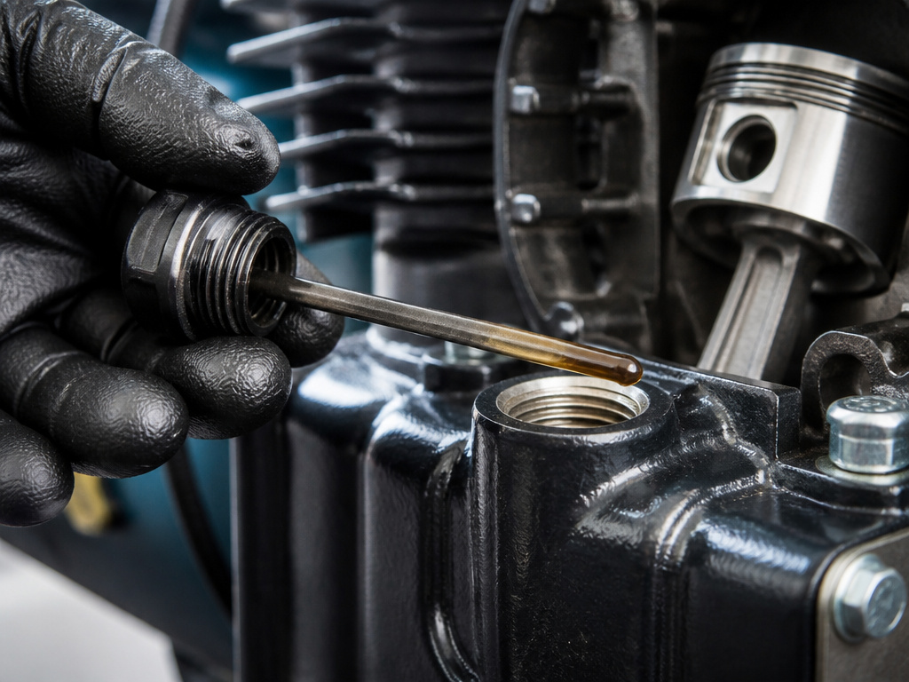
This choice isn’t about quality; it’s about application and maintenance tolerance. The pump’s mechanism needs lubrication to prevent metal-on-metal wear. How it gets that lubrication splits the world in two.
Oil-Lubricated Compressors have an oil sump that bathes the crankshaft, bearings, and cylinder walls (in piston types) or floods the rotor chamber (in screw types). This oil cools and seals components.
- Cons: Requires regular oil checks and changes.
Manufacturers specify exact oils. Ingersoll Rand, for example, recommends their All-Season Select® synthetic from start-up. If using a petroleum-based alternative, they mandate a flashpoint of 440°F (227°C) or higher and an auto-ignition point of 650°F (343°C) or higher. They also provide a viscosity guide based on ambient temperature (ISO VG 32 for under 40°F, VG 100 for 40-80°F, etc.).
Oil-Free Compressors use permanently lubricated bearings or coatings like Teflon on the compression surfaces. The air chamber itself runs dry.
- Pros: Zero risk of oil contamination in your air.
Matching a Compressor to Your Tools: CFM & PSI
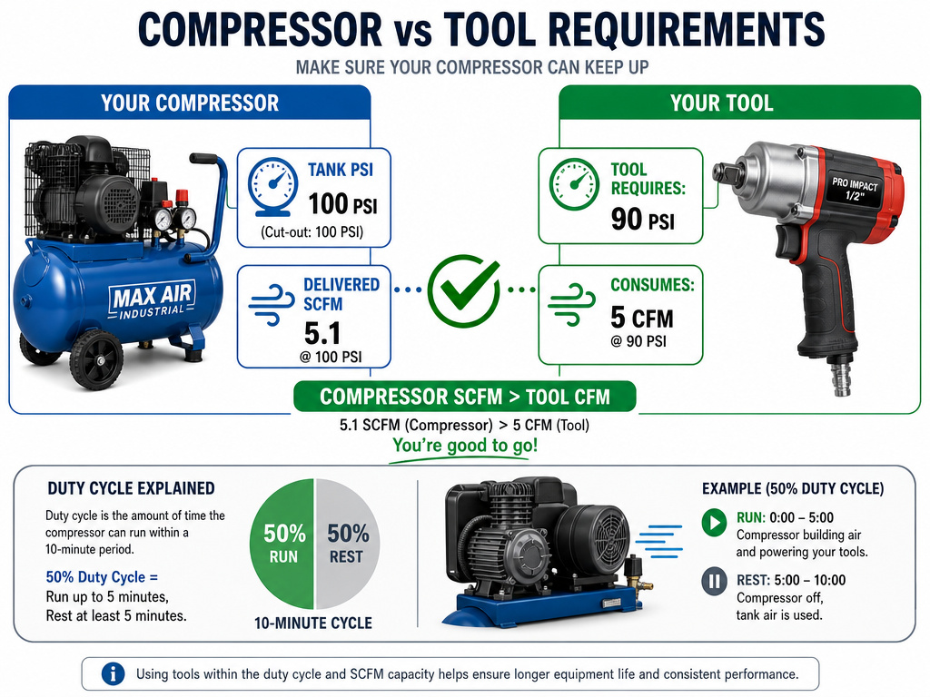
This is where theory meets the wall. Your compressor’s specs must meet your tool’s demands, or you’ll be waiting more than working.
PSI (Pounds per Square Inch): This is the pressure your tool needs to operate. Most air tools require 70-100 PSI. Your compressor’s maximum pressure must exceed this, and you’ll use the regulator to set it. The tank’s pressure switch cut-out (e.g., 100 PSI) defines the upper limit of your system’s pressure.
CFM (Cubic Feet per Minute): This is the volume of air your tool consumes. This is the critical number. You must look at the tool’s CFM requirement at the PSI you’ll be running it. A tool might need 5 CFM at 90 PSI.
- Displacement CFM: The pump’s theoretical maximum. A Sears Model 919.174211 has an 8.8 CFM displacement.
- Delivered CFM (SCFM): The actual air volume the compressor delivers at a given pressure. That same Sears model delivers 5.1 SCFM at 100 psig and 6.6 SCFM at 40 psig. Notice how delivery drops as pressure rises. Always use the delivered SCFM at your required PSI for comparison.
Your compressor’s duty cycle is also key. A 50% duty cycle means it should only run for 30 minutes in every hour of operation. Exceed that, and you overheat the motor. For continuous tools like sanders, you need a 100% duty cycle compressor (like a rotary screw) or a much larger tank to reduce motor cycling.
Essential Maintenance & Safety
A compressor is a pressure vessel. Ignoring maintenance isn’t just about breakdowns; it’s a safety risk. The manuals aren’t just suggestions.
Daily/Weekly:
- Drain the Tank. Every single day. Condensation is inevitable. CPO Powertools’ manual states moisture “must be drained at the end of every workday to prevent corrosion of the tank from the inside.” In cold climates, drain after each use to prevent freezing. This is so critical we have a full guide on how to drain an air compressor tank.
- Check the Oil (if oil-lubed). Maintain the oil level as specified by the manufacturer.
- Inspect for Leaks. Listen for hissing, especially at connections and the drain valve.
Monthly/Seasonally:
- Check the Air Filter. Clean or replace it as needed.
- Test the Safety Valve. Pull the ring to confirm it opens and releases pressure, then let it snap closed.
Annually/By the Book:
- Change the Oil (if oil-lubed). Follow the manufacturer’s interval. KAESER mandates an oil change after the first 50 operating hours of a new machine.
- Inspect the Tank. Look for external rust. Internally, corrosion is the enemy. For larger industrial units, formal inspections are law. KAESER’s manual, referencing pressure vessel regulations, states an internal inspection is required every 5 years and a strength test every 10 years for receivers with a pressure/volume product ≤ 1000.
Safety First:
- Use Proper Electricals. Don’t run a 15-amp compressor on a 16-gauge, 100-foot extension cord. Voltage drop will overheat the motor. Ingersoll Rand states for wire distances not exceeding 50 feet (15.3 m), use the wire sizes shown in the wire selection chart.
- Install Safely. Use flexible hose at the compressor discharge to absorb vibration. Slope all air piping downward in the direction of airflow to permit condensate to drain properly, as per Ingersoll Rand’s installation guide.
Single-stage vs. Two-stage compression
The main difference is how many times the air gets squeezed before it’s stored. A single-stage compressor compresses air from atmospheric pressure to the final tank pressure in one motion. A two-stage compressor does it in two steps, with an intercooler cooling the air between stages. This two-step process reduces the heat generated during compression, which improves efficiency for higher pressure demands. The choice depends on your required pressure and duty cycle. For continuous, high-pressure industrial work, two-stage is often the better choice.
Drive types (belt vs. Direct)
This refers to how the motor connects to the compressor pump. In a direct-drive system, the motor shaft is connected straight to the pump crankshaft, making it compact. In a belt-drive system, a set of pulleys and a belt transfer power from the motor to the pump. Belt drives allow for speed adjustment by changing pulley sizes, which can match the pump’s optimal speed to the motor. They also isolate the motor from some pump vibration. Your choice affects maintenance, noise level, and the ability to fine-tune the compressor’s output speed.
Difference between a pump and a compressor
While both move fluids, the key difference is what they move. A pump is designed to move liquids, like water or oil. A compressor is specifically designed to move gases, like air, and increase their pressure by reducing their volume. For example, a compressor working at a typical pressure can compress air to one-eighth of its original volume. This fundamental difference dictates their internal design, sealing methods, and how they handle the heat generated during operation, as gases are compressible and liquids are not.
Frequently Asked Questions
Is a 20-gallon air compressor big enough for air tools?
It depends entirely on the tool’s CFM demand. For a framing nailer (2-3 CFM), a 20-gallon tank is massive overkill. For a 6 CFM orbital sander, a 20-gallon tank on a compressor that only delivers 5 SCFM will be constantly cycling on and off, and you’ll wait for recovery. The tank just buys you time; the pump’s SCFM output is what does the work.
How do air compressors get power?
Most stationary shop compressors use a single-phase or three-phase electric motor. Portable job-site compressors often use gasoline or diesel engines. The power source needs to match the motor’s specifications (voltage, phase, amperage) exactly to avoid damage.
Should you leave an air compressor on all the time?
No. You should turn it off and depressurize the system when not in use. Leaving it on keeps the pressure switch engaged and the motor under electrical load, which is a safety risk and wastes energy. It also keeps pressure on all seals and hoses, accelerating wear.
Do air compressors refill themselves?
Yes, but only automatically when connected to power and in “Auto” mode. The pressure switch controls this. When air use drops the tank pressure to the “cut-in” setting (e.g., 80 PSI), the switch activates the motor to refill the tank to the “cut-out” pressure (e.g., 100 PSI). If the switch is in “Off,” or the unit is unplugged, it will not refill.
Before You Go
Don’t get hypnotized by tank size or peak horsepower. The single most important question is: what is the highest continuous CFM demand of any tool I’ll run? Find that number, then find a compressor whose delivered SCFM at your working PSI meets or exceeds it. A compressor that can’t feed your hungriest tool is just a noisy, expensive tire inflator.
Remember the water. That 85 liters in an 8-hour shift isn’t a hypothetical; it’s physics. Install a moisture trap, drain the tank religiously, and you’ll add years to your equipment’s life. Finally, respect the duty cycle. If you need to run a sander for more than a few minutes at a stretch, you’re in the market for a compressor built for continuous work—your ears and your patience will thank you.
